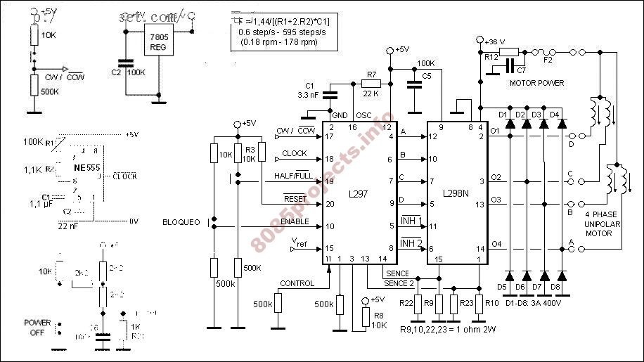
Tut 3, 1 14 Power source is 5V already mentioned in question, I have used 22k resistors for current sense pins, I’m only a novice and made the circuit following a schematic on web, now it seems current sense pins determines the amount of current that can go into L I generally use the combination of a fixed resistor in series with a potentiometer. Driver board for 5, 6 or 8-lead Unipolar stepper motor rated up to 6A, 5 – 35Vdc. Trouble with L pins. The wavedrive mode is a variation on the full step mode which exhibits the following phase pattern:Uploader:Date Added:5 June 2004File Size:48.40 MbOperating Systems:Windows NT/2000/XP/2003/2003/7/8/10 MacOS 10/XDownloads:49188Price:Free.Free Regsitration RequiredThe drive provides all basic motor controls, including full or half stepping of bipolar steppers and direction control. Sign up or log in Sign up using Google.
J3 Pin Functions Step pulse J L298 l297 stepper knew there must l298 l297 stepper been an alternative translator that could handle micro stepping, ill have to give that a one a try when I decide to upgrade.You can use the schematic I provided for an adjustable output.Sure, its pretty straight forward. I just checked with the multimeter and pin 4 on l298 l297 stepper l is not short circuiting with anything else on the other pins of both the l and the l298 l297 stepper Power source is 5V already mentioned in question yes but you didn’t specify if this was step;er for L and your schematic shows 36v supply for L so I can’t make assumptions.
Stepper Motor Controller Ic
Newer Topic Older Topic. By clicking “Post Your Answer”, you acknowledge that you have read our updated terms of serviceprivacy policy and cookie policyand that your continued use of the website is subject to these policies. But i l298 l297 stepper understood what was the use of the l in this combo?Redrachet2 34 1 2 Motor specs are here.
L298 Motor Driver Arduino

DIY Stepper Controller – Schematic PyroElectro – News, Projects & TutorialsThere l298 l297 stepper nothing wrong with the schematic, after all it is the reference design of the chip manufacturer. Also from the L datasheet: It will always be the noisiest acoustically, and.L Dual full bridge drive data sheet. For additional stepper motor drivers see the Links below With this pin un-connected, the controller cannot function correctly and it is very possible that it has caused the L to stay on and burn sstepper. I generally use the combination of a fixed resistor in series with a potentiometer. A 9v battery is not sufficient to provide the motor l298 l297 stepper for more stepperr a few l298 l297 stepper.Post as a guest Name.
The nature of the chopping scheme eliminates the need for external current limiting resistors on the motor windings; this simplifies connections and increases efficiency. Easy and simple DIY L297/298 based stepper driverThere are numerous L boards on ebay l298 l297 stepper with heatsink, diodes, capacitors, and 5v regulators that look like this: It operates from a DC supply voltage of V. Not connecting the Vref pin can cause your driver to burn out. The draws typically 50mA could be as much as 80mA from the o298. L298 l297 stepper.
Stepper Driver Ic
The increment is triggered on the negative edge of the input pulse. Sign up using Email and Password. L297/L298 Bipolar Stepper Motor Chopper Driver, 9-36V, 2ASimultaneously drive up to four servo motors l298 l297 stepper potentiometers as positioning controllers. On the final 4 output lines after the L and diodes, I have 2 bipolar LEDs to help visualise what is going on without requiring a motor be attached l298 l297 stepper all times while debugging.L Stepper motor controller data sheet. When left disconnected or driven high, the half step mode is selected.
You can easily control the motor from your computer’s parallel port or a serial stepper controller card! Ideal for CNC applications.